555 Mono Stable Circuit Complete Beginner Guide
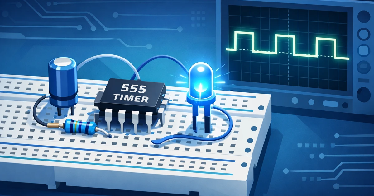
Hero image alt text: 555 mono stable circuit with 555 timer IC, resistor, capacitor, LED output, and pulse waveform.
The 555 mono stable circuit is one of the simplest ways to create a controlled time pulse in electronics. If you press a button, trigger a sensor, or need a short delay, this circuit can turn one input event into one stable output pulse. In this guide, you will learn how the 555 timer works in monostable mode, how to calculate pulse duration, how to choose components, and how to troubleshoot common issues with confidence.
Key takeaways
- A 555 mono stable circuit produces one timed output pulse after a trigger event.
- The pulse width depends mainly on one resistor and one timing capacitor.
- Good layout, clean triggering, and smart component selection improve circuit optimization and high quality results.
What Is a 555 Mono Stable Circuit?
A 555 mono stable circuit, also called a monostable multivibrator, stays in one stable state until it receives a trigger signal. After triggering, the output switches high for a calculated period, then returns low automatically, making it useful for delays, pulse shaping, switch debouncing, alarms, and sensor timing applications in practical circuits.
A 555 mono stable circuit uses the classic 555 timer IC in a one pulse mode. In normal conditions, the output remains low. When the trigger pin briefly goes low, the output turns high and stays high for a set time.
That time is controlled by a resistor and capacitor. Once the capacitor charges to a set threshold, the 555 timer resets the output. This makes the circuit predictable and easy to adjust.
Common uses include:
- Push button delay circuits
- LED flash pulses
- Relay activation timers
- Sensor output stretching
- Switch debounce circuits
- Simple pulse generator circuit designs
The 555 timer remains popular because it is cheap, widely available, and reliable. According to the Texas Instruments NE555 datasheet, the device can operate across a broad supply range and support timing and pulse generation applications.
If you publish technical tutorials, clear explanations matter as much as accurate wiring. Leadmetrics shares practical guidance on content structure, visibility, and optimization through its digital marketing blog, which can help teams turn useful guides into searchable resources.
How the 555 Mono Stable Circuit Works and Uses the Timing Formula
The circuit works by charging a timing capacitor through a resistor after the trigger input receives a short low pulse. The output stays high while the capacitor charges. When the capacitor voltage reaches two thirds of the supply voltage, the internal comparator resets the timer and returns the output to low again.
Inside the 555 timer IC, two comparators, a flip flop, and a discharge transistor control the output. The trigger pin detects when voltage drops below one third of the supply voltage. This starts the timing cycle.
During the timing cycle, the discharge transistor turns off. The timing capacitor begins charging through the timing resistor. The output pin goes high.
When the capacitor reaches two thirds of the supply voltage, the threshold pin resets the internal flip flop. The output returns low, and the discharge pin quickly discharges the capacitor.
A basic 555 timer pinout for monostable operation is:
- Pin 1 connects to ground
- Pin 2 is the trigger input
- Pin 3 is the output
- Pin 4 is reset and usually connects to supply
- Pin 5 is control voltage and often uses a small capacitor to ground
- Pin 6 is threshold
- Pin 7 is discharge
- Pin 8 connects to supply voltage
The 555 mono stable circuit is powerful because one short input can create a clean, longer output. For example, a noisy mechanical button may produce several tiny transitions. A monostable circuit can convert that into one useful pulse.
This is also why engineers use the 555 timer circuit for practical education. It shows clear cause and effect, much like data analytics shows which inputs affect results in a measured system.
The standard 555 monostable timing formula is:
T = 1.1 × R × C
In this formula:
- T is the output pulse width in seconds
- R is the timing resistor in ohms
- C is the timing capacitor in farads
For example, if you use a 100,000 ohm resistor and a 10 microfarad capacitor, the pulse duration is about:
T = 1.1 × 100,000 × 0.00001
T = 1.1 seconds
This means the output stays high for about 1.1 seconds after the trigger. If you increase the capacitor to 100 microfarads, the pulse becomes about 11 seconds.
Use these practical guidelines:
- Use a stable resistor value for predictable timing
- Use a quality capacitor for longer delays
- Avoid very high resistor values when accuracy matters
- Add a small capacitor on pin 5 to reduce noise
- Keep timing components close to the IC
Electrolytic capacitors can have wide tolerance. A 10 microfarad capacitor may not measure exactly 10 microfarads. If accuracy is important, measure the capacitor or use tighter tolerance parts.
The All About Circuits 555 timer guide provides helpful background on how internal comparators and timing networks shape 555 operation.
Choosing Values for a 555 Mono Stable Circuit
The best resistor and capacitor values depend on the delay you need, the accuracy required, and the physical size of the parts. Short pulses often use smaller capacitors and moderate resistors. Longer delays need larger capacitors, but leakage and tolerance can reduce timing accuracy.
Start by choosing a capacitor value that is easy to buy and physically practical. Then calculate the resistor. For simple breadboard projects, values between 10,000 ohms and 1,000,000 ohms are common.
If you need a pulse around half a second, try a 47,000 ohm resistor and a 10 microfarad capacitor. The result is close to 0.52 seconds. If you need a longer delay, increase the capacitor first, then fine tune the resistor.
Example timing values:
- Target pulse 0.1 second: 91,000 ohms with 1 microfarad
- Target pulse 1 second: 91,000 ohms with 10 microfarads
- Target pulse 5 seconds: 470,000 ohms with 10 microfarads
- Target pulse 10 seconds: 910,000 ohms with 10 microfarads
Component selection is a form of circuit optimization. For companies publishing product education or technical explainers, the same test and refine mindset applies to search visibility. Leadmetrics supports AI-driven search engine optimization with data analytics and tailor-made digital marketing strategies that help useful technical content reach the right audience.
Building the Circuit and Troubleshooting Common Problems
Building a 555 mono stable circuit is straightforward when you wire the power pins first, connect reset properly, add the timing resistor and capacitor, then connect the trigger and output. A breadboard makes testing easy, but careful wiring matters because loose connections, noisy power, and long trigger leads can cause unstable pulse timing.
Before building, gather these parts:
- NE555 or LM555 timer IC
- Breadboard
- 5 volt to 12 volt power supply
- 10,000 ohm trigger pull up resistor
- Timing resistor
- Timing capacitor
- Push button or sensor trigger
- LED and current limiting resistor
- 0.01 microfarad capacitor for pin 5
- Optional 0.1 microfarad supply bypass capacitor
Follow these steps:
- Connect pin 1 to ground and pin 8 to the positive supply.
- Connect pin 4 to the positive supply to disable reset.
- Connect pin 5 to ground through a 0.01 microfarad capacitor.
- Connect pins 6 and 7 together.
- Connect the timing resistor from positive supply to pins 6 and 7.
- Connect the timing capacitor from pins 6 and 7 to ground.
- Connect pin 2 to a push button trigger circuit.
- Connect pin 3 to an LED through a current limiting resistor.
- Add a 0.1 microfarad capacitor near the IC power pins.
When the push button pulls pin 2 low, the output on pin 3 turns high. The LED lights during the pulse. When timing ends, the LED turns off.
A clean trigger signal is important. If the trigger stays low longer than the timing period, the circuit may not behave as expected. A short pulse at pin 2 gives the most reliable operation.
If your circuit controls a relay, motor, or buzzer, use a transistor driver when needed. Do not overload the 555 output. Also add a diode across relay coils to protect the IC from voltage spikes.
Troubleshooting a 555 Mono Stable Circuit
Most 555 mono stable circuit issues come from wiring mistakes, noisy power, incorrect trigger behavior, wrong capacitor polarity, or poor breadboard connections. Troubleshooting works best when you check the power rails, verify each pin, measure the timing capacitor voltage, and test the output with a simple LED first.
If the output never turns high, check pin 4 first. The reset pin must connect to the positive supply. If reset is low, the output remains disabled.
If the output stays high forever, check the timing capacitor and pins 6 and 7. The capacitor may be reversed, disconnected, or unable to charge properly. Also confirm the discharge pin is connected correctly.
If the pulse time is wrong, measure the actual resistor and capacitor values. Capacitor tolerance is often the main cause. For long delays, leakage current may also affect the result.
Use this troubleshooting checklist:
- Confirm pin 1 is ground and pin 8 is positive supply
- Confirm pin 4 is tied high
- Confirm pin 2 normally stays high before triggering
- Confirm pins 6 and 7 share the timing node
- Check timing capacitor polarity
- Add supply decoupling near the IC
- Test the output with an LED before adding loads
- Use a transistor for higher current devices
Reliable Triggering in a 555 Mono Stable Circuit
False triggering is another common issue. Long trigger wires can act like antennas. Keep trigger wiring short, add a pull up resistor, and consider a small capacitor for noise filtering.
If you use the circuit in a product or demonstration, document every test result. Good engineering notes help you compare changes. For businesses publishing technical content, a marketing audit and data analytics review can show which tutorials support lead generation and which pages need better optimization.
Practical Applications of a 555 Timer Circuit
A 555 timer circuit in monostable mode solves many real world timing problems. It can stretch a short sensor signal, debounce a switch, create a fixed alarm pulse, delay a relay, or trigger a visible LED event. This makes it useful for students, makers, technicians, educators, and product prototyping teams.
A 555 mono stable circuit is often used when a system needs one consistent output pulse. For example, a door sensor may only create a very short signal. The 555 timer can stretch that signal into a longer pulse that activates a buzzer.
Another example is button debouncing. Mechanical switches can bounce many times within milliseconds. A monostable circuit can turn that messy input into one clean pulse for another circuit.
Useful applications include:
- Camera shutter delay projects
- Toy sound trigger circuits
- Home alarm pulse timers
- Relay delay activation
- Touch sensor output extension
- LED notification pulses
- Simple educational lab experiments
The 555 timer is not always the best choice for advanced precision. Microcontrollers offer programmable timing, and modern timer ICs may provide better accuracy. Still, the 555 is excellent for simple, low cost, hardware based timing.
The value of the circuit is clarity. You can see the trigger, timing capacitor, and output behavior directly. That makes the 555 mono stable circuit a strong learning tool.
For teams turning technical projects into articles, product notes, or demand campaigns, clarity can support better lead generation. Leadmetrics provides tailor-made digital marketing strategies for businesses that need structured content, measurable workflows, and high-quality results.
If your company creates educational guides, a technical tutorial can also become part of a broader AI-powered digital marketing strategy. The goal is not just to publish information, but to connect practical knowledge with measurable audience demand.
Conclusion
A 555 mono stable circuit gives beginners and makers a practical way to create one timed output pulse from one trigger input. By understanding pin functions, timing math, component tolerance, and trigger behavior, you can build more reliable delay circuits while also improving how technical ideas are documented, explained, and shared.
The 555 mono stable circuit is a reliable way to create a single timed pulse from a trigger event. It uses a simple resistor capacitor timing network, follows the formula T = 1.1 × R × C, and works well for delays, switch debouncing, alarms, relays, and pulse generator circuit projects. Start with clean wiring, choose sensible component values, and test with an LED before adding larger loads. If you apply the same structured testing mindset to business growth, Leadmetrics can help with AI-powered optimization, data analytics, and tailor-made strategies that support lead generation and high-quality results. To explore a practical growth plan, you can book a demo with Leadmetrics.
Leave a Reply